PCB Isolation Routing
Overview
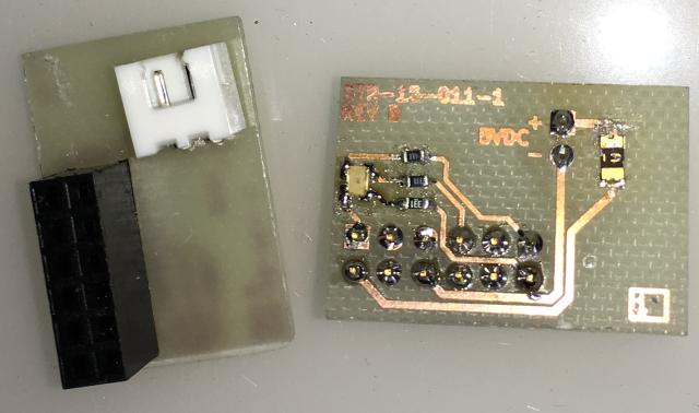
Most of my work is using 0603 sized discrete components.
Calibration
I perform two types of calibrations for PCB isolation routing when using copper-cam but same can be applied to whatever cam software is being used to mill the PCB.
This ensures that the values I have within my software are correct physically, as a v-bit width of cut is dependant on the depth of cut. Additionally the best sweet spot of the cutting speed is determined.
Width of Cut Calibration
I originally found information about this calibration here: http://phk.freebsd.dk/CncPcb/calibrate.html, but it was in eagle PCB format, Ive since converted to KiCad and ultimately as a common gerber file.
To find the optimal cutting depth for a V-Bit I use gerber file in copper-cam that steps through track sizes 1-25 mil and track spacings of 1-25 mil.
The object is calibrating the width of cut (WOC) for a given bit within the cam software (copper-cam in this case) and the actual cut on PCB, it also gives and indication of the smallest traces and track clearances achievable with the given bit.
Basically you put in the settings into coppercam for the cutter and run the this grb, then measure under a microscope the actual width of cut, make diameter adjustments back in the software to compensate, then re-run and hey presto your cuts should be correct widths. Its also a good way to test what the cutter is capable of.
The problem with Vbits are the width of cut can vary due to copper layer variation, how level your machine is and how deep you cut and is why I go for lower angle cutters of 10-30Degrees and shallow cuts.
Example
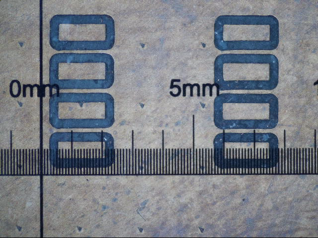
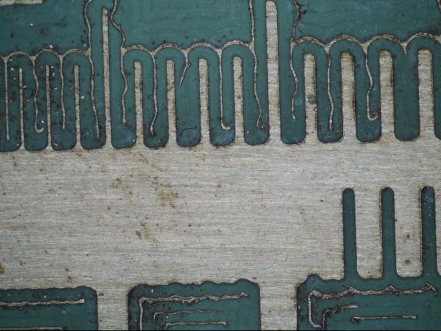
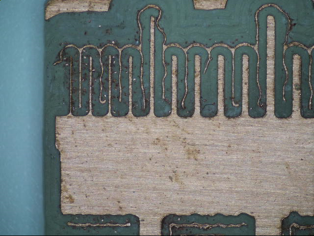
These two images below are for the WOC or bit width calibration within the Copper-cam, i.e. bits are not normally the size they are suppose to be so the diameter is tweaked in the cutting software, when the upper traces = the lower gaps it means that the bit size in the software is set correctly.
Smallest track size on Left of screen is 1mil (1 thousand of inch) also I don't yet have my step-over dialled in and hence why I have some copper artefacts left because of the difference between the advertised cutter size VS calibrated cutter size.
So with the bit diameter calibrated it is showing me that minimum track width is 1mil and min track clearance is 12mil This was done with a 30Deg V-Bit The calibration test starts at traces 1mil up and increments by 1 up to 25 mil this is done on both Traces and Clearances.
Feeds, Speeds and Depth settings.
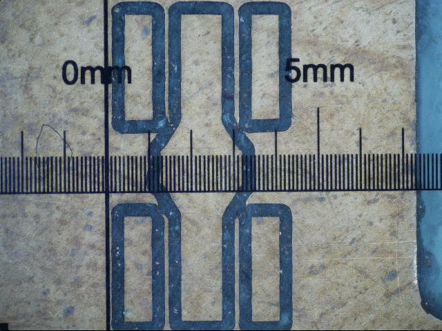
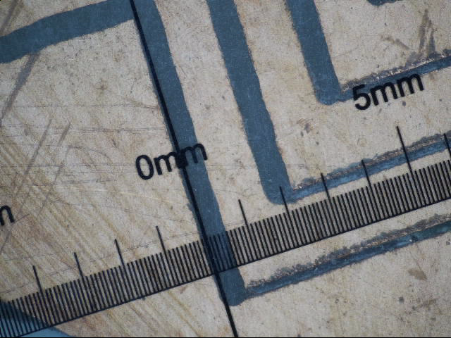
These are calibration cuts at different feeds and depth, ones showing is for 0.050mm depth of cut, again the ragged edge is VBit engraving bit. Measurement ruler is in 0.1mm increments.
So with my 20Deg Vbit I'm getting ~0.2mm width of cut
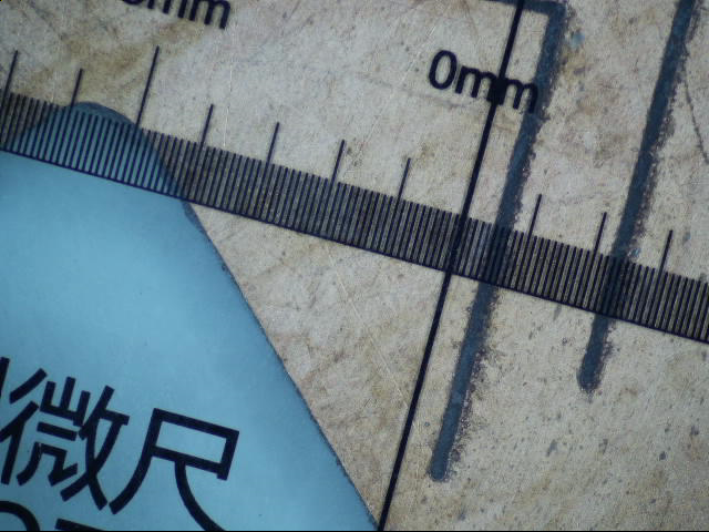
0.4mm width of cut using end mill
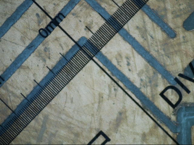
0.6mm width of cut using PCB Burr Cutter
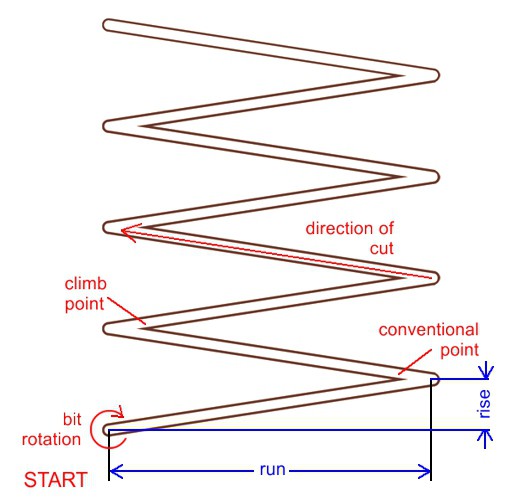
Sweet spot test for Feed and speed
To find the optimal or sweet spot for the feed and speed of a PCB cutter I use the following process:
https://www.precisebits.com/tutorials/calibrating_feeds_n_speeds.htm
The attached gcode runs through a range of feeds and spindle speeds using the zigzag pattern outlined on the above link
Example
Bits used are:
-
20 Deg 0.1mm Engraving VBit
-
0.4mm end mill
-
0.6mm PCB Burr Cutter
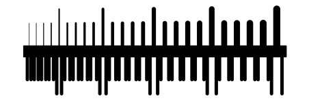
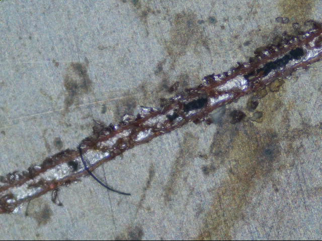
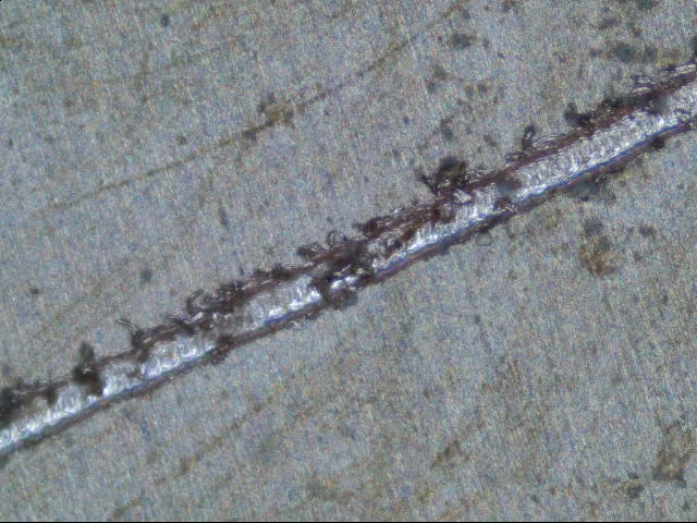
You can see the quality of cuts vary between the types of cutter, so is a trade of using the V-bit for the very fine work which give a ragged cut as opposed to very clean cuts for the end mill and PCB cutter. (the board is easily cleaned up with fine emery board or wet n dry so is not an issue)
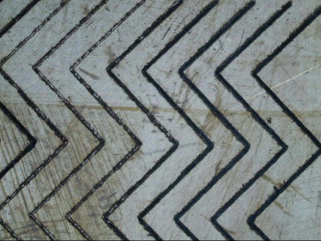
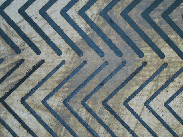
Here you can see zoomed in that the fine tipped V-Bit does not like faster feed speeds as it starts to deflect and not cut properly, sort of bounces over the surface and not cutting deep enough.
zigzag g-code
see gcode library
Challenges
Auto levelling
Currently I don't probe the surface of the PCB as the controller wont perform automatic Z-axis compensation like MACH4 or LinuxCNC does (the only downside I found so far of using the standalone controller vs PC controller), this is whats really needed for v-bits to compensate the depth of cut for the irregularities of the copper substrate surface so that the width of cut remains constant.
I use a plate of aluminium as my bed that's been recently surfaced to my machine, this works well for me currently and don't really need z-axis compensation.
One workaround to the v-bit issue and not having Z-axis compensation via surface probing is to use a micro mill cutter, this way all WOC are consistent no matter the depth of cut.
Another method, yet still un-tested, is the DDCS V3.1 controller does allow a surface to be probed and written to a file on the USB, this probing file can be read by g-code ripper and a surface mapping can then be applied to the generated PCB g-code generated by copper-cam.
Related blog post: http://www.scorchworks.com/Blog/auto-probing-with-g-code-ripper/
DDCS support was added in v0.22 of g-code ripper.
Created: 2021-10-22